4 minutes
What I know about Ecodan ASHPs
Summary
The following is a meandering post on what I’ve learnt about heat pumps (and more specifically the Ecodan range from Mistubishi) and some handy resources I’ve found.
The System
The gist of the sytem is shown in the following infographic.
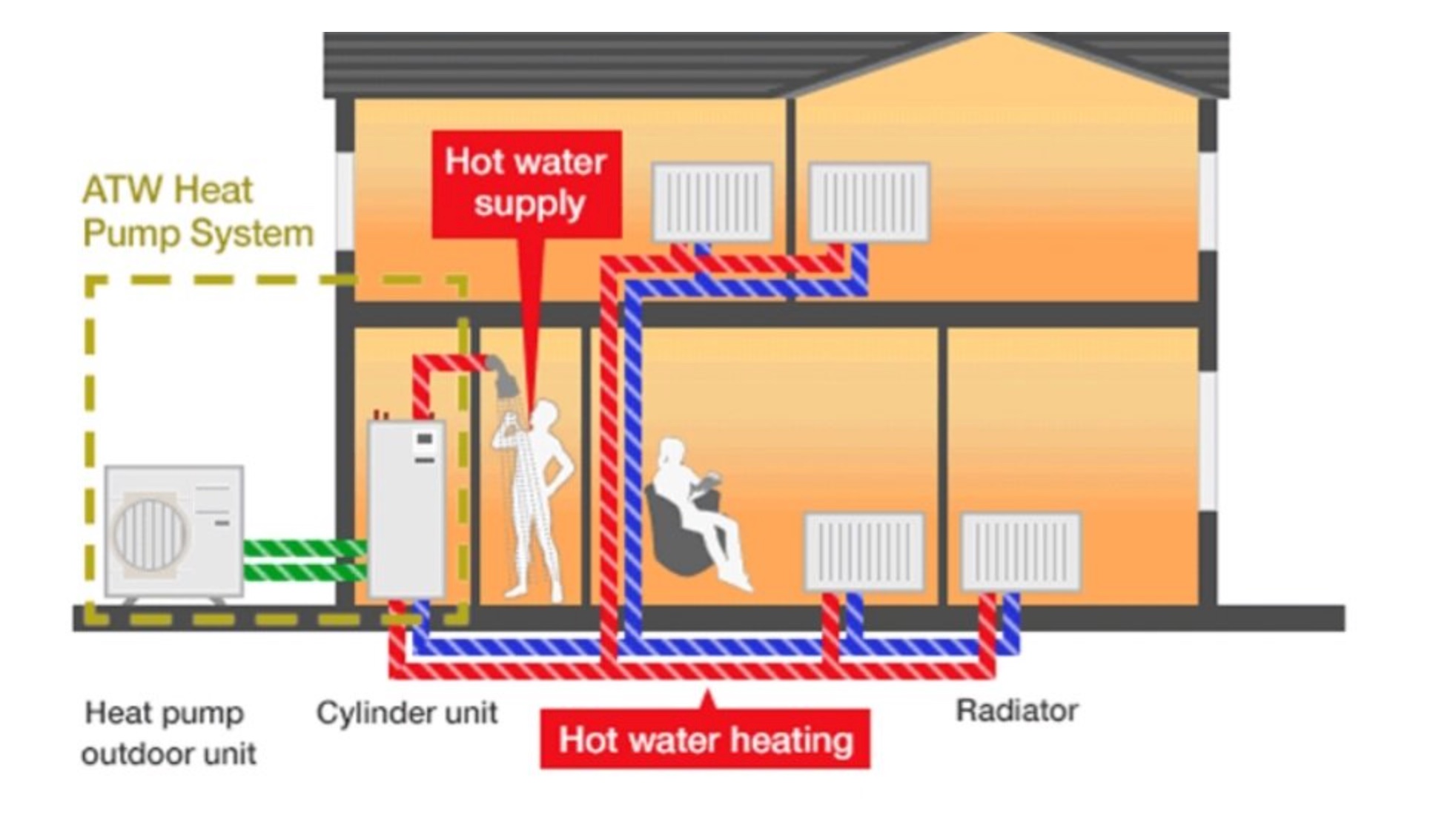
The Outdoor Unit
I’m using an 5kW Mitsubishi Ecodan Air to Water Heat Pump. It uses R32 as its refrigerant. It’s a Monobloc unit, this means that the refrigerant is all contained outdoors and only water migrates into the house.
There are two sides to every heat pump, the source and the sink. One can think of the source (air passing through the fan outdoors) as the input and the sink as the output (our radiators, etc). In this case, our source is Air and our sink is Water.
- Ecodan PUZ-WM50VHA Information Sheet
- Ecodan PUZ-WM Installation Guide
- Ecodan PUZ-WV50VHA (OCH727) Service Manual
The Indoor Unit (Cylinder Unit)
Judging by the label on the unit, this an EHPT17X-VM2DR1.UK model. The 17 in the title means that it has a 170 litre DHW (Domestic Hot Water) tank.
The Controller
This system uses the FTC6 controller. From our point of view, this consists of a collection of dip switches for initial setup and then an LCD display for modifying on the go.
- Ecodan FTC6 Instruction Book
- Handy video explaining the dip switches on the FTC6.
- Covers some of the points on two zone systems.
Map of the Plumbing
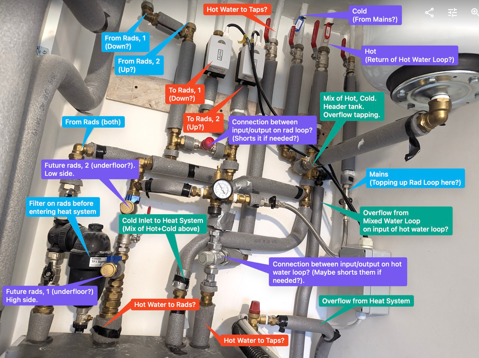
The following image is a map of the pipework above the cylinder unit, with labels. Some of this is based off the labels attached to the pipes and other parts are guesswork.
DHW Details
- There are two feeds of water coming in.
- One of these is labelled cold; I think this comes from the tank in the attic.
- (It could be coming from mains but I don’t think it is because it’s coming down from the ceiling so seems like an unlikely path).
- The other one is labelled hot. I think this is a return path from the hot water that orginates from the cylinder unit.
- One of these is labelled cold; I think this comes from the tank in the attic.
- These mix together and go into the heat pump.
- There is also a header tank here and an overflow.
- These then come back out and go out again towards all three of the hot water taps and the shower.
Radiator Details
- Starting from the left, I think these are two return paths for the radiators.
- They combine together and then enter a filter before going into the unit.
- (The filter is a Fernox TF1 Sigma Filter, which has a 10 year warranty).
- TF1 Sigma Filter 28mm Data Sheet
- This data sheet shows how to clean the filter also.
- The heated up fluid then comes out of the cylinder unit, from the second pipe from the left.
- There are two tap points here with a valve between.
- I think this is to allow for an underfloor heating loop to be added on conveniently.
- This hot line then goes up and branches into two separate lines.
- Each line has a motorized control valve on it.
- (Adjusting the thermostats in the rooms seems to have an effect on these, lighting them up).
- EPH V222PW Installation & Technical Spec Document
- There are two tap points here with a valve between.
Other Details
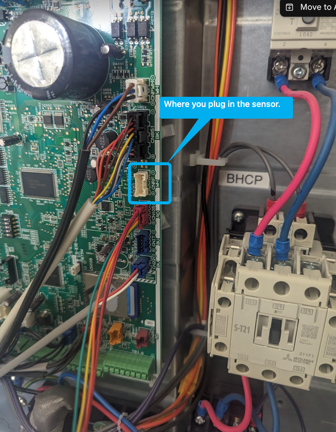
Adding a smart sensor
It’s possible to add a smart sensor to this heating system. The model number I used was 587IF-E.
When I was trying to source this, there was confusion online about the fact that there are multiple variants. It seems like there’s a different part number for Austrialian models (or something).
I bought mine on eBay and it seemed to work fine.
For installation, I used the following videos:
Diagnostics
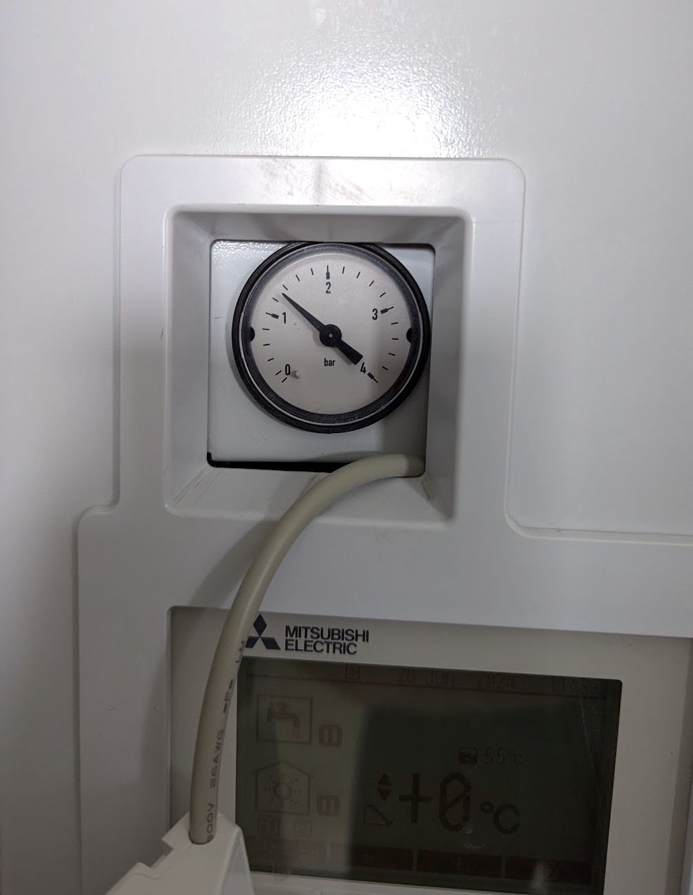
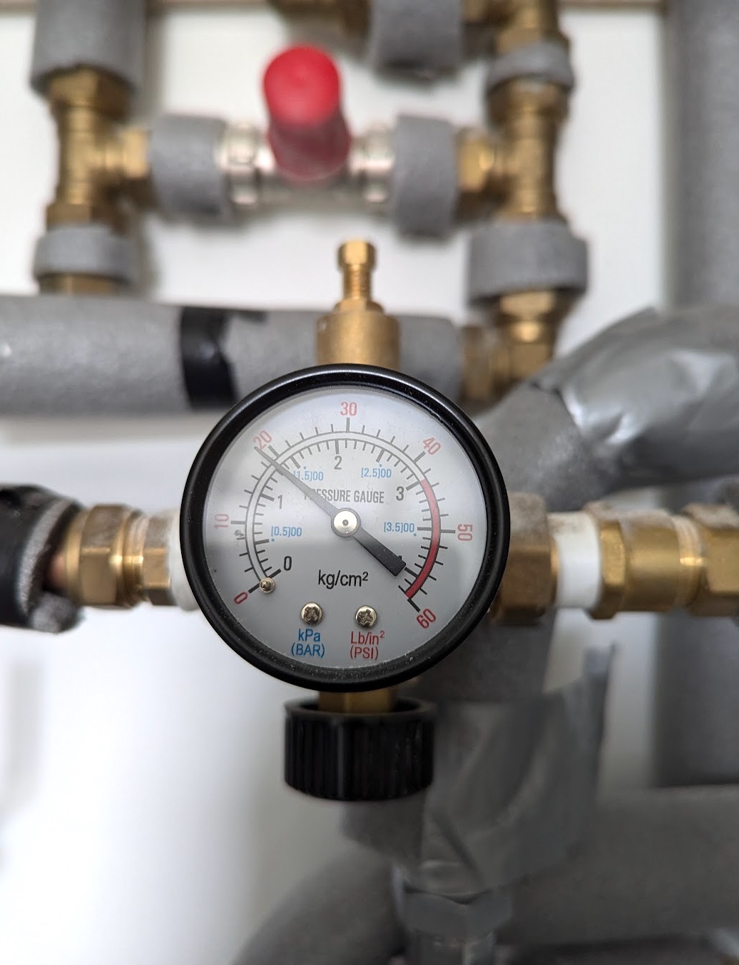
Pressure Gauge
- Previously I had a slight weep in the system. There’s a gauge that indicates the pressure of the system.
- From talking to the plumber and heat pump service guy, keeping it in the range of 1 to 2 bar is what you’re looking for, they advise.
Links
- The book Heat Pumps for the Home was pretty good.
- It actually includes a lot of systems that use Ecodans.